Construction Guidelines for Bruce's Candy Drop Assembly
This is a small project that I always wanted to do with the SFK, but never seemed to get around to it. Finally,
with our local club's airshow coming up, it seemed like the perfect time. There are lots of good ways to
install a candy drop in your model; the assembly shown here is just one approach. I had three requirements
for my candy drop assembly: 1) It had to be a removable, self-contained unit, 2) It needed to be installed
with minimum "trauma" to the model, and 3) The doors should be able to close after dropping the load. Your
personal requirements or desires may be different, so treat the following details as guidelines rather than
cold, hard instructions. In fact, with some re-sizing, you could adapt these guidelines to make a candy drop
assembly for just about any high-wing cabin model
|
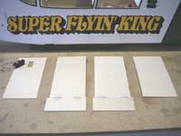 Cut the main parts. The box sides are cut from 1/8" lite-ply. All four sides are 6" wide and 12" tall.
I cut the pieces with the outer ply grain parallel to the 6" dimension. That makes them a little floppy to
handle now, but ultimately resulted in a stronger box. The doors were cut from 1/8" aircraft ply
for extra stiffness. Both doors are 2-13/16" x 6-5/8". Notice the doors are cut extra long so there will be
some hangover at the front side of the box. I've already cut the servo hole in the top of the box's front face,
leaving about 1/16" clearance all around.
|
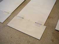 Prepare the hinges. I used Sig XX-Hinges, two per door, just because that's what I had lying around.
A small piano hinge would have been a little cleaner, but the nylon hinges have worked well so far. The sides
and doors required notches to clear the hinge knuckles. Dab some vaseline on the hinge line, then melt
it in with a quick blast from a Monokote heat gun. After this photo was taken, I covered my doors with Monokote
because it seemed easier to do it now than it would be later.
|
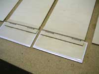 Lock the hinges in place. The idea was to glue the hinges in place without
the need for screws sticking in or out of the box. I started by cutting 1/2"-wide strips of 1/32" plywood to
serve as filler material between the hinges. CA was used to glue the filler strips in place. Then I cut 1/2"-wide
strips of 1/8" aircraft ply to lay across the hinges. The edges of the plywood nearest the hinge were beveled
to avoid hitting each other with the doors closed. The hinges and plywood strips were carefully epoxied in place,
weighted down, and allowed to dry.
|
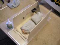 Make a box. It's finally time to make it look like something. I used lead-filled bean bags to hold one
side firmly on the table. The front and rear box faces were butted up against the edge of the side and glued with
CA. Notice the metal triangle used to make sure the parts are square to each other. Don't forget the wax paper!
Flip the unit over to install the second side.
I added 1/2" balsa triangle stock the full length of each joint for extra strength. You now have a beautiful
plywood box with a couple of floppy doors on the bottom. Cool!
|
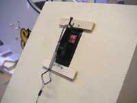 Install the servo. Okay eagle eye, it was already installed in the previous photo! Be sure
to use the rubber grommets and hardware. I installed the servo from the inside in order to keep the arm
as close to the box as possible. A retract servo was chosen because it has high torque, moves through 180
degrees, and again, it's what I had lying around. The 1/16" music wire hook uses a Z-bend and wheel collar
to attach it to the servo arm. The most important thing is to position the servo arm so that it is vertical
when the doors are shut, to minimize the stress on the servo.
|
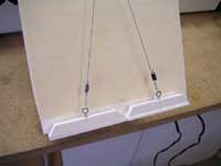 Add anchor blocks and eyelets. On the overhanging front edge of each door, I added strips of 1/4" x 3/8"
basswood to serve as anchor blocks for the screweyes. Full movement of the servo arm is 2-1/2". Armed
with that knowledge, I carefully measured the doors for proper placement of the eyelets. The first test (see
next pic) showed the doors didn't open completely - so much for careful measurements! I never claimed that
I always do things right the first time... A small shift in the eyelet position gave better results.
|
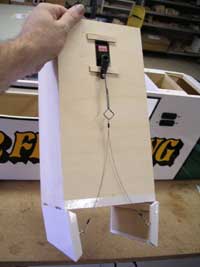 Complete the linkage. The cable linkage was fabricated with the same materials I use
for tail braces; nylon-coated steel cable and steel crimps. Be sure the cable is pulled fairly tight when the
doors are closed and goes slack when the doors are open. Notice I covered the anchor blocks and a small portion
of the box. Other than that, there is no finish (paint, covering) on the box. I don't intend to use it often,
and the gas motor on my SFK puts out very little exhaust residue.
Give it a test. Using an extension, my servo was plugged into channel 5 on one of my receivers. That way,
I could use the retract switch on the transmitter to open the doors. I've read in the past where some guys use
light springs to open the doors, but I decided to rely on the weight of the payload to push its way out. One nice
thing about the double doors is that you can land the model with the doors down without worrying about scraping
them on the ground.
|
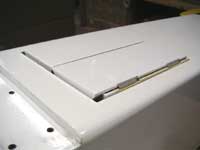 Minor surgery. The plan was to cut an accurate hole in the lite-ply on the bottom of the fuselage,
then use the cutout piece to plug the hole later. I took some measurements with the box inside the fuse, and
carefully transferred those measurements to the bottom surface (here we go again with measuring - but this time
it worked!). I left 1/32" clearance on each side, zero on the back, and about 1/8" at the front. The photo shows
the box installed. I allowed it to protrude about 1/4" to eliminate any chance of the doors hanging up on the
fuselage structure.
|
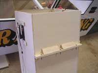 Add the side rails. My SFK already had hardwood rails glued into the cabin area just below the windows,
so I decided to utilize them for the mounting of the box. Box rails were cut from 1/4" x 1/2" spruce. The fuselage
was propped up from my table 1/4", then the box was put in place resting on the table. I slid the spruce rails
in position and tack glued them to the box using medium CA. The box was removed, triangle
braces were added for strength, then the box was re-positioned and three screw holes were drilled
through the rails on each side.
|
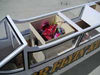 Load it up. I used socket-head wood screws to hold the box to the airframe; they can be installed with
a ball driver. The photo shows
my SFK at the field ready for its trial run as a Candy Bomber. Although I was pretty confident it would work,
there was no time to test it before the show. The kids were in for a real treat, or a big disappointment. The
box was loaded from the top, and it soaked up a FOUR-POUND bag of candy with no problem. In addition to the candy,
we put in about eight little toy parachutes.
|
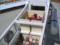 Final Preparation. The connector for the servo was taped to the rear of the box just to keep it from
flopping around. Notice that the top of the box goes right up to the bottom surface of the wing, so there's no
need for a "lid". One note of caution: Be sure your retract switch is in the "doors up" position when you turn
on the radio, or you will instantly dump your load. Believe it or not, I haven't made that mistake (yet!). Also,
line up helpers to keep the kiddy crowd back until the candy is released. One of the helpers should have extra
candy for the little ones who may not get any.
|
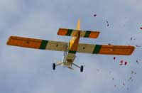 Bombs away! This great shot was taken by fellow club member, Joe Stagg. Four pounds of candy raining
from the sky is almost as impressive as the thundering herd of kids dashing out to scoop it up. The parachutes
were a fun addition - some of the bigger kids skipped the candy and followed them downwind. Of course, the model
was flown safely in a holding pattern some distance from the field until the runway was cleared of people. It
was a big hit with the crowd, and a fun way to end the airshow.
|
Some final thoughts... The overall weight of the candy drop assembly was only 14.5 ounces. That means with
a full load of candy, my SFK was hauling about a five-pound payload. As you might expect, I couldn't even begin to
notice a difference in performance. Interestingly, when the candy was dropped, my SFK chugged along without
the slightest burble or bump in altitude. The open doors had no effect on handling. In all, it was a satisfying
project that took less than a day of work and was well worth the effort. Just ask the kids!
|
<Back To Super Flyin' King Page
|


