by Bruce Tharpe

Click to Enlarge This conversion can be performed on your Flyin' King model at any time whether you are just starting construction or have already been flying with glow/gas power. The situation with the model shown below is somewhat unique. It is an airframe that was previously built and prepared for a glow engine, but never covered or finished. In fact, it is the same exact model that was originally built for the FK instruction book photos about 18 years ago. I finally found a good excuse to finish it! If you are starting with a fresh kit, it should be easy to do the conversion as you build. If you are starting with a finished model that has been flying, go ahead and remove the engine, fuel tank, throttle servo, and anything else related to your original powerplant. Clean the model inside and out as best you can before starting the conversion.

Click on any of the photos for a larger image. If you have any questions that are not answered here, please contact me directly and I will do my best to help.


QUICK INDEX TO ASSEMBLY MANUAL TOPICS

Motor Standoff Assembly
Prepare the Firewall
Hatch Construction
ESC Installation
Arming Switch (Optional)
Sliding Battery Tray Installation
Battery Selection
Battery Charging Info
Propeller Selection


MOTOR STANDOFF ASSEMBLY

The electric motor needs to be mounted about 1-3/4" forward of the existing firewall (F-1) to put the propeller at the same position it would be with a glow/gas engine. This plywood standoff is simple, strong, and solid. It was designed to mount in the same spot as a Hayes motor mount shown on the FK plans and used by lots of BTE customers. The parts can all be glued with medium or thick CA. Once built, it can be left as bare wood or finished with paint. I used clear dope to seal the wood and white Lusterkote sprayed from a can for color.

Click to Enlarge Click to Enlarge Click to Enlarge


PREPARE THE FIREWALL

Electric-powered models need a supply of fresh air to cool the motor, ESC, and battery. So you will need cut some inlet holes in the firewall (F-1). If you are building a new model, it will be easiest to cut the cooling holes before gluing F-1 into the fuselage assembly. The cooling air also needs an outlet. Fortunately, the Flyin' King has a natural outlet at the rear of the fuselage where the elevator pushrod exits. This arrangement worked fine for cooling in my test model. If you feel the need for more outlet area, you can leave a small portion of the fuselage bottom in front of the tailwheel mount uncovered.

Click to Enlarge Click to Enlarge Click to Enlarge


HATCH CONSTRUCTION

A nose hatch is needed for quick-and-easy installation and removal of the flight battery. Again, your actual steps will depend on whether you are building a fresh kit or converting an already-built model. The hatch uses rare earth magnets to snap it in place on the model so it can be opened and closed without tools.

Click to Enlarge Click to Enlarge Click to Enlarge
More About the Magnets
These magnets are strong! If they come in contact with each other, they are very difficult to pry apart. So when they are installed in the fuselage and the hatch, you need to maintain an air gap of 1/32" to 1/16". Glue a magnet into each of the magnet mount holes so that the bottom of the magnet is flush with the bottom of the plywood. Thin CA works well to glue the magnets. You can actually fill the gap above the magnet with medium or thick CA. Important! Before you glue the opposing magnets into the hatch bottom, you need to confirm they are oriented properly. In one direction they attract. Flip it over and they will repel each other. Once you are sure the polarity is correct, glue the magnets into the hatch bottom with thin CA.

Warning! These magnets are not toys - handle them with care
1. Neodymium magnets are brittle; they can be broken or can splinter in a collision. One should wear gloves and protective glasses when handling these magnets, because splinters and/or spacers could disengage and fly from the magnets.
2. Normal Neodymium magnets will lose their magnetic properties if heated above 175°F (80°C).
3. The strong magnetic fields of neodymium magnets can damage items such as television, computer monitors, credit cards, bank cards, computers, diskettes and other data carriers, video tapes, mechanical watches, hearing aids, loud speakers and VCRs. Pace-makers may be damaged or switch to "Test Mode" in the presence of a strong magnetic force, if a pace-maker or other electrical body implant is in use, keep a minimum of 3 feet distance.
4. Children should not be allowed to handle neodymium magnets as they can be dangerous. Small magnets pose a choking hazard and should never be swallowed or inserted into any part of the body.
5. Under no circumstances should you try to cut, saw or drill the Neodymium magnets! Not only would the magnet break, but the resulting dust from the magnet is very flammable. Neodymium magnets should never be burned, as burning them will create toxic fumes.


ESC INSTALLATION

The Cobra 80-Amp ESC (Electronic Speed Control) takes the place of the throttle servo. It is mounted near the bottom of the hatch opening which is good for cooling, easy hook-up with the arming switch, and it stays out of the way of the sliding battery tray. The ESC does require you to install connectors on all of the wires. Female bullet connectors are supplied with the Cobra ESC, and they will match up perfectly with the bullet connectors on the motor. As for the battery wire, you will have to choose your preferred connector (not included). Follow the links below for help with connectors.

Click to Enlarge 
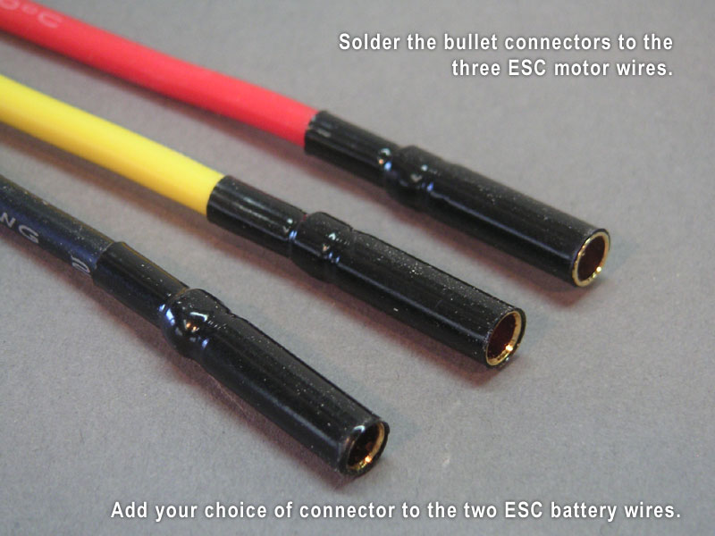
New to soldering bullet connectors? This will help:
YOUTUBE: How to Solder Bullet Connectors - Innov8tive Designs

More videos on popular battery connectors:
YOUTUBE: How to Solder a Deans Connector - Innov8tive Designs
YOUTUBE: How to Install Anderson Powerpole Connectors
YOUTUBE: Soldering XT60 Connectors
Click to Enlarge Click to Enlarge Click to Enlarge


ARMING SWITCH (OPTIONAL)

Well, technically it's optional, but most electric models of this size are fitted with some sort of arming switch for safety. An arming switch is not included in the conversion package, but it is highly recommended. I used one from Maxx Products that is relatively inexpensive and doesn't require assembly. The anti-spark feature works, but is really not necessary for a 6S LiPo battery. If you attach the arming plug without using the ant-spark button first, you will hear a tiny arc as the circuit completes, but it's harmless. Be sure to get an extra arming plug to carry in your flight box at all times as a backup.

The position of the mount plate shown on the plans allows clearance for the ESC below and the sliding battery tray above.

Click to Enlarge Click to Enlarge Click to Enlarge

Here's a link to the
Maxx Products Arming Switches. The one shown above is #6994.


SLIDING BATTERY TRAY INSTALLATION

So your chunky flight LiPo needs to go in and out through a relatively small hatch opening in the nose and be fastened securely somewhere in the cabin area. To do that, we are going to strap your battery to a plywood plate that slides into rails on each side of the fuselage interior. Ultimately, you want to position your flight battery as necessary for your desired balance point, which may actually change as you get used to the model's flying characteristics. You can alter the battery position (and therfore the balance point) by simply changing the plywood spacers used between the sliding battery tray and the tray stop at the rear. A Velcro retention strap is used to keep the battery from sliding forward in flight.

Click to Enlarge Click to Enlarge Click to Enlarge
Click to Enlarge Click to Enlarge


BATTERY SELECTION

BTE recommends a six-cell lithium polymer battery with a capacity of 5000mAh for this electric power package. This is a fairly common size for high-power models. You will see it listed as 6S-5000 LiPo battery in ads and on websites. If you are new to electric power, you may be surprised at the wide price range from different vendors, from $50 to $60 at the low end to over $200 at the high end. You will also find various C-ratings, which is linked to the battery's internal resistance and its maximum safe discharge current. And in general, the higher the C-rating, the higher the price. Luckily, you do not need a high C-rating for this power package to operate efficiently. Any C-rating of 15C or more will work fine.

I do not have vast experience with electric power and cannot fairly recommend one brand of battery over another. You can slog through the debates in the online forums if you want, but a better approach might be to ask a more-experienced member of your club what he or she uses. Personally, I have avoided the very cheapest batteries and gone with several in the $75 to $90 range, and so far they have all worked well.


BATTERY CHARGING INFO

Large batteries require a powerful charger. Again, you will find a variety of chargers with a variety of features, specs, and prices. At the very least, you will want a charger that can handle a single 6S battery at a charge rate of 5 amps. That requires 125 watts (25 volts x 5 amps = 125 watts). You are encouraged to do your own research, but I will tell you what I settled on. The iCharger 3010B will output 500 watts of power with a 12V power supply or 1000 watts of power with a 24V power supply. It will charge up to 10S batteries which is overkill for now, but it gives me room to grow in the future. It is certainly not the cheapest option, but I'm a serious modeler and prefer to invest a little more in good equipment that will be used for many years to come.

Using the technique of parallel charging, I can charge up to four 6S batteries at the same time with this charger at a 1C charge rate (5 amps). It is nice to go to the field with more than one fully-charged battery. Having to charge batteries at the field for more flights can add to the complexity of electric flying depending on the situation. If you are lucky enough to fly from an electric-friendly field with power supplies and charging stations, that's great. If not, you will need to bring your own source of power such as a deep-cycle marine battery or generator.


PROPELLER SELECTION

If you are new to electrics, you will quickly learn that the power you get involves more than the motor. The motor, battery cell count, and propeller all work in unison to pull your airplane along. For max efficiency, they all need to be tested together and tailored to suit the model they are used in. The Cobra 4130/16 motor with the supplied APC 16 x 10E propeller and a 6S battery has been proven to work efficiently in the Flyin' King with minimal heat build-up.

One of the reasons I chose Cobra motors in the first place was because Innov8tive Designs provides comprehensive propeller charts for all of their motors. Here is a link to the
Cobra C-4130/16 Propeller Data Chart. You can see from the chart that switching to a different propeller can possibly lead to over-stressing the motor or a significant power loss. Stick with what works!


    <Back to previous page


home | venture 60 | flyin' king | delta vortex | super flyin' king | reaction 54 | about bte | prices | ordering | in the works


pilots | cable cutters | fourmost | handibond | builder galleries | plans page | double whammy | uav projects | vintage rc

© 2016 Bruce Tharpe Engineering  |  e-mail BTE: bruce@btemodels.com