
Flyin’ King Towline Attach and Release
by Al Clark
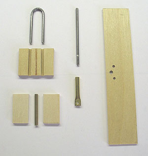
The towline attach and release consists of a few pieces of plywood, some music wire, and some brass tubing. Photo 01 shows the parts and the partially assembled plywood plate for the U shaped music wire.
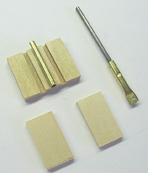
Make the wire parts first from 3/32 diameter music wire. The U shaped piece is about 1/2 inch wide across the outer edges. You can make the release pin a little long now, and trim to exact length later. Make a small notch in the release pin on opposite sides, near the bottom, using a Dremel tool carbide cutting wheel.
Cut a piece of 3/32 I.D. brass tube 1 inch long, and another piece of 1/8 I.D. brass tube 1 inch long. Rough up the smaller piece and glue inside of the larger piece using 5 minute epoxy. Make sure to keep the inside of the nested tubes clear of glue. When the glue has cured, flatten the last 1/4 inch or so of the nested tubes using a vise or good pair of pliers. Drill a 1/16 diameter hole through the center of the flattened area.
Rough up the end of the release pin (where the notches are) with sandpaper, and glue the nested brass tube in place using J.B. Weld epoxy. Crimp the brass tube into the notches on the release pin using the wire cutter portion of your pliers.
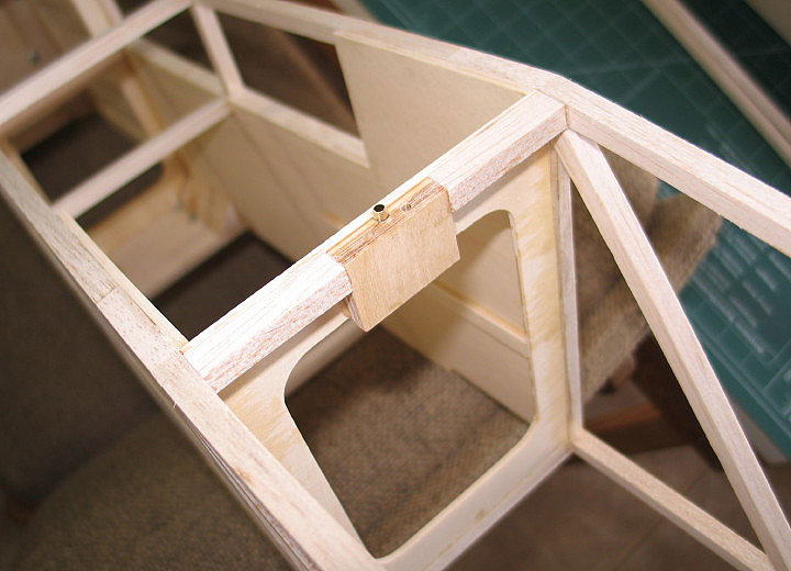
Cut a plate of 3/32 plywood to match the depth of the top section of former F3. The width isn’t critical – mine was around 1 and 3/8 inch wide. Glue 3 smaller pieces of 3/32 plywood onto the plate, leaving two slots for the U shaped piece of music wire (use the U shaped music wire to properly position the pieces, but don’t glue in the wire yet). I used thick CA to glue these pieces together.
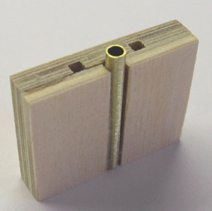
Cut a piece of 3/32 I.D. brass tube that is 3/32 inch longer than the height of the 3/32 plywood plate. This extra length will be needed later when the load plate is installed. File or sand a slight groove into the center piece on the plywood plate assembly. Slide the release pin assembly into the brass tube and check the fit – the idea here is to allow the side of the release pin to almost touch the U shaped music wire when all the parts are in place. When satisfied with the alignment, glue the brass tube to the plywood plate assembly using a little CA.
Now glue a piece of 1/8 inch plywood on each side of the brass tube, and sand the plywood faces slightly to be flush with the brass tube. You should end up with a laminated plywood block that looks like photo below (left). Note the brass tube sticks out 3/32 inch on top.
Glue the plywood block assembly to the aft side of former F3, on center, and add a piece of 5/16 square balsa on each side (see photo below). Make sure the top of the plywood block assembly is flush with the top of F3.
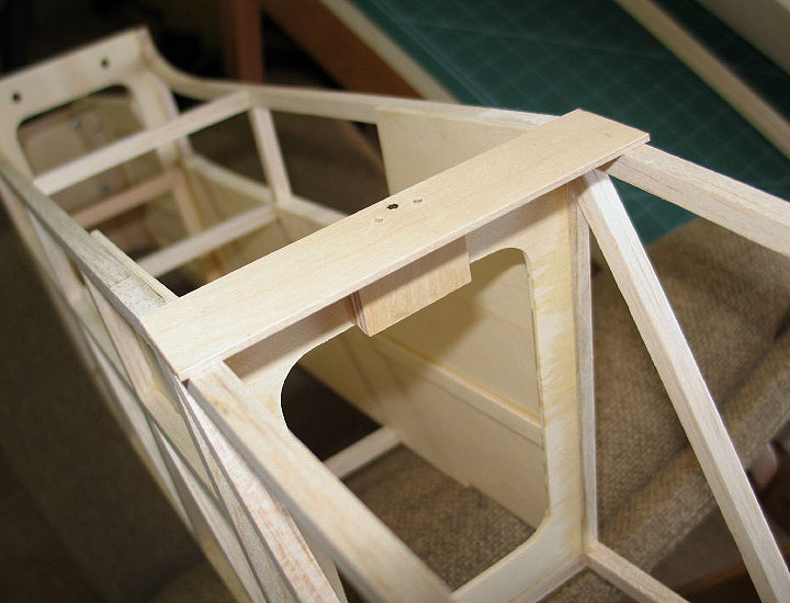
If you haven’t already done so, make up the 3/32 x 1 inch wide plywood load plate. See photo 1 for a good view of the load plate. Three holes need to be located precisely and drilled to match the plywood block assembly. The front hole is 1/8 diameter and the two rear holes are 3/32 diameter. Check the hole alignment by putting the plate in place with the brass tube in the front hole. Now check to make sure the U shaped music wire will slide into the plywood block assembly. When satisfied that everything fits, glue the 3/32 plywood load plate to the plywood block assembly, top of F3, and to the upper fuselage longerons. Make sure to clear any glue out of the holes, especially where the U shaped music wire goes.
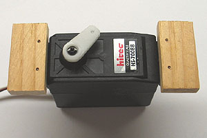
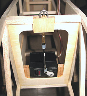
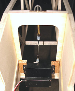
Mount a powerful servo to two 1/4 inch blocks of spruce or pine. The servo is mounted from underneath (see photos below). I used a Hitec 1/4 scale servo because I had a spare one lying around.
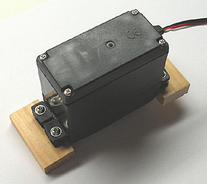
Trim the outer edges of the blocks to just fit inside the fuselage, and glue the blocks to F3, with the servo on the front side, and the top of the servo pointing aft. The photos below show the servo position from the rear and from the front. You want to keep the servo mounted low to clear the rudder and elevator pushrods.
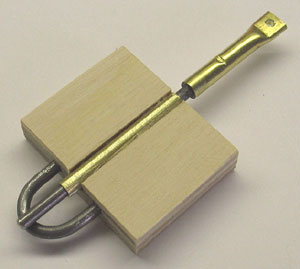
Now make up a short 4-40 sized pushrod using a 4-40 solder link and 4-40 adjustable quick link. Slide the release pin into the brass tube, hook up the short pushrod, and adjust the position of the servo arm. Use your transmitter throw adjust to set the travel. You want the release pin to be slightly above the U shaped music wire in the line attached position (see bottom photo), and below the fuselage top in the released position. Trim any excess length from the release pin at this time.
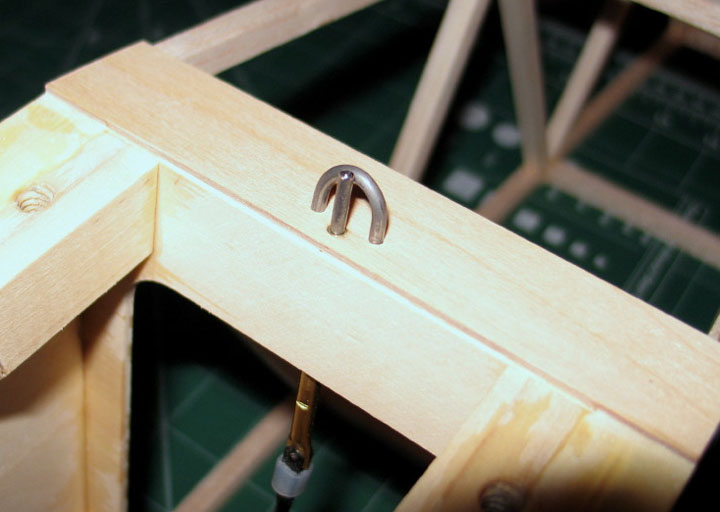
I sheeted the entire top of the fuselage, aft of the 3/32 plywood load plate, with 3/32 cross grain balsa to help distribute towing loads, and added diagonal braces on the bottom between fuselage bays, to help with torsional rigidity. I did not glue in the U shaped piece of music wire until after I had the fuselage covered. I then installed it with some 5 minute epoxy.
Now, you are ready to tow! I have found that with an O.S. 1.20 AX two stroke engine and Zinger 16x8 prop, the Flyin’ King can tow sailplanes up to about 10 lbs. Good luck and have fun!
<Back to Al in Alabama