
Flyin' King Drop Box Installation
by Al Clark
This drop box requires the Flyin’ King to be built as a taildragger. The design is simple, utilizing the existing fuselage sides as part of the box. The door is designed to open fully, leaving nothing to cause a potential snag or hang-up to whatever you want to fall out of your box when you command the door to open. To make this drop box you will need to delete the fuselage plywood bottom that is installed aft of the plywood landing gear mounting plate.
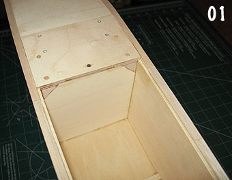
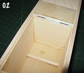
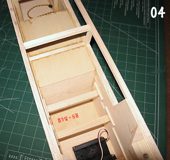
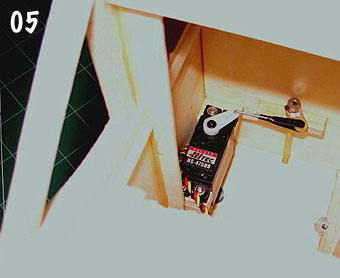
Make the forward box wall and aft box wall from 1/8 Lite Ply with the grain running across the fuselage. The forward wall is aligned flush with the aft end of the plywood landing gear mounting plate and will therefore need to have the corners cut to clear the landing gear plate triangular reinforcements (photo 01). The aft wall sits on top of the 5/16 square cross brace that is about 9 inches behind F2 (photo 02). Make sure you put a notch in the edge of the forward and aft walls to clear the throttle cable housing. Exterior views of the forward and aft walls are in photos 04 and 05. The sides of the box are simply the already existing Lite Ply fuselage doublers.
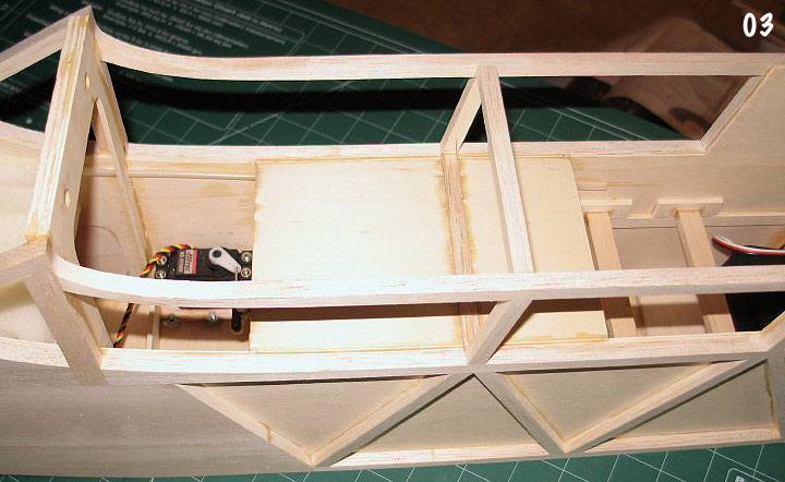
The top of the box is made from 1/16 plywood with the grain running fore and aft. It is in two pieces, one in front of the 5/16 square cross brace that is about 6.25 inches behind F2, and one piece behind (photo 03). The pieces are fit so they end up flush with the top of the fuselage window openings. You will now have a box that is about 4.125W x 4.75H x 6L.
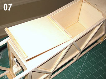
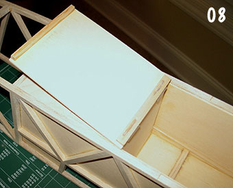
Make the door from a flat piece of 1/8 Lite Ply with about 1/32 clearance all around. The grain should run fore and aft. Add a 3/8 wide piece of 1/8 Lite Ply across the aft end and a piece of 1/4 square spruce across the front edge. Make sure these pieces stop about 5/32 inch short of the outer edges of the door so they will clear the fuselage doublers when the door is closed. See photos 06, 07, and 08.
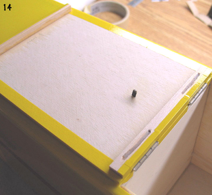
Obtain some heavy duty pinned hinges (I used 7/8 inch wide Klett hinges) and cut hinge slots, at a 45 degree angle, into the door and into the fuselage cross brace. You will need to notch the door slightly and the fuselage cross brace slightly to allow the hinges to fit low enough so the hinge pin is aligned with the bottom surface of the fuselage. See photos 02, 07, and 08. Dry fit the hinges and make sure the door fits and opens/closes properly. Drill a 1/32 diameter hole through the door, 1.25 inches from the hinge end, centered side to side. Refer to photos 12 and 14 to see where the hole is located. This hole is used for the opening cable after the door is installed.
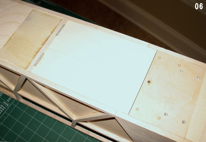
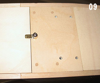
Make the door release tab from 1/16 x 1/4 brass stock. The length is 3/4 inch. Solder this tab to a 1/8 I.D. wheel collar, then drill through the wheel collar and brass using a 1/8 diameter drill bit (photo 09). This tab will be attached to a piece of 1/8 diameter music wire that is actuated by a servo. A brass tube must be installed through the plywood landing gear plate as a bearing for the 1/8 diameter music wire. Drill a 5/32 diameter hole through the plywood landing gear plate, located 5/16 inch from the edge and centered side to side (photo 06). Cut a piece of 1/8 I.D. brass tubing about 2.5 inches long (you might need to adjust the length depending upon what kind of servo you mount to actuate the release). Position it in the hole in the landing gear plate so that the tube sticks out 1/32 inch. This will allow clearance for the brass plate that will be added later to the door. CA the tube to the landing gear plate. Inside the fuselage, install a piece of scrap wood, with a 1/8 diameter hole, at the top of the tube to hold it in place (photo 05).
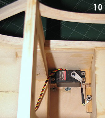
Make up another brass tab with a soldered on wheel collar, identical to the one you made for the door release tab. Drill a 1/16 diameter hole through the tab, near the end, for the pushrod (you might want to drill a couple extra holes, closer to the wheel collar, to allow for throw adjustment later). Install the tab onto the end of the 1/8 diameter music wire which goes down through the brass tube to the release tab on the bottom of the fuselage. Mount a servo onto the right fuselage side using wood blocks glued to the fuselage doubler. Make up a short pushrod with a Z bend on one end, and adjustable clevis on the other (photo 10). You can experiment with the position of the servo arm and the throw to get 90 degrees of travel on the release tab.
Add some 1/8 Lite Ply about 2 or 3 inches wide to the bottom of the fuselage, just behind the fuselage cross brace at the rear of the drop box. This piece should be flush with the fuselage bottom and the grain should run across the fuselage (photo 02). This piece of Lite Ply will hold the eyelet for the pull cable that will be installed later.
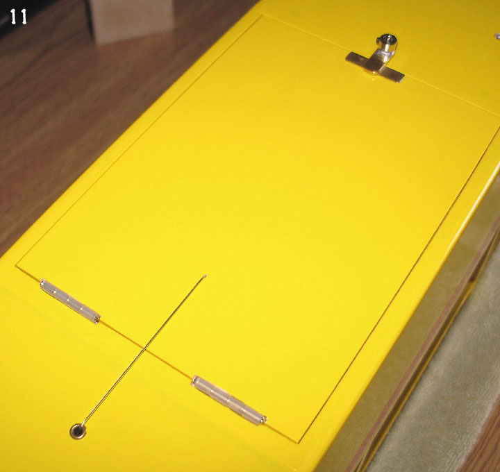
After the door has been covered with film, remove covering from a 1/4 x 1 inch area at the forward end and glue on a piece of 1/32 x 1/4 x 1 brass stock, centered side to side (photo 11). This is the wear plate for the release tab to slide against. Carefully glue the door hinges into the door. Make sure the hinge pins are aligned properly. After the fuselage has been covered, glue the door hinges into the slots in the fuselage, making sure the door is positioned properly. You can use epoxy for this, or CA+ if you are brave. When the glue has cured on the hinges, open the door 180 degrees, against the aft fuselage. Use a pin through the 1/32 diameter hole in the door to mark the fuselage. Close the door, and drill a hole through the fuselage to fit a small eyelet (I used a small servo mounting eyelet). Glue the eyelet into the hole. It should all look like photo 11, minus the cable, which we haven’t installed yet.
Glue two small notched plywood plates to the inside of the fuselage, at the top, just at the rear of the window openings. These will hold a piece of 1/8 diameter music wire (photos 15 and 16). This music wire will hold the end of the spring which is connected to the door pull cable. Cut a piece of 1/8 diameter music wire to fit across the fuselage, and slide on two 1/8 I.D. wheel collars (don’t tighten yet).
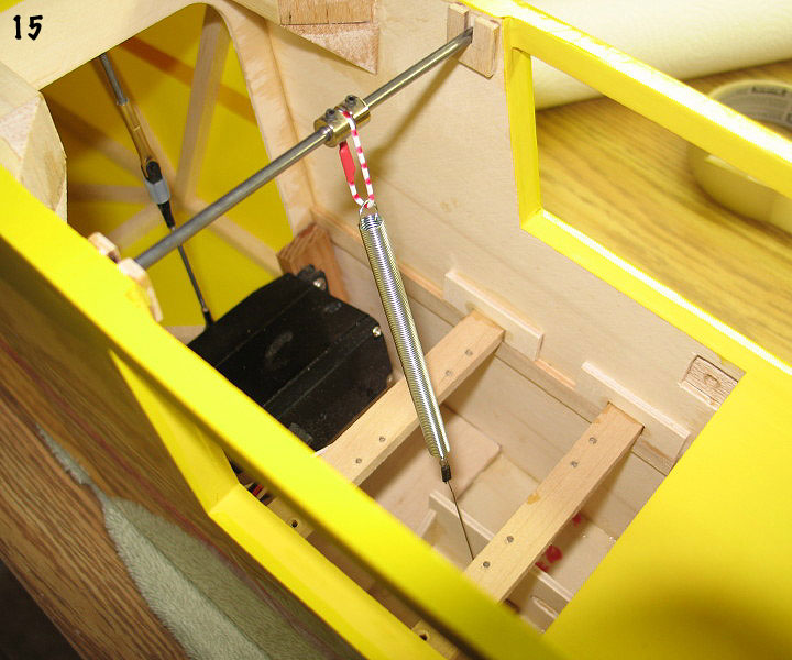
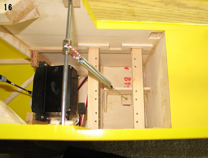
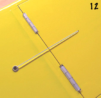
Look at photos 12 and 16 and you will see how the pull cable and spring are arranged. These photos show the spring and cable position with the door open. For cable I used some plastic covered steel fishing leader, and the crimps are the small copper type that Proctor sells for cable rigging. You can also use small brass tubing for crimps. One crimp should be on the inside of the drop box door (photo 14). The length of the cable should such that the spring has just enough tension to hold the door open against the bottom of the fuselage. When the door is closed, the spring will be stretched. I used a piece of paper clip as a length adjustment on my setup to get the correct tension. I got the spring at home depot – it is about 1/4 diameter and 3 inches long. Adjust the position of the wheel collars on the 1/8 diameter music wire, inside the fuselage, so that the spring clears the mounted servos.
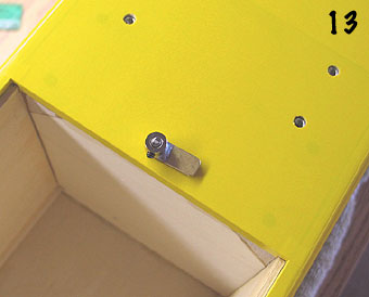
Photo 13 shows the release tab in the open position and photo 14 shows the door open, held by spring tension against the bottom of the fuselage. You might also want to add a small piece of thin, high density, foam rubber on the fuselage bottom to align with the rear of the door when it is open. This will cut down on the wear to the covering material.
The drop box will take on about 3.5 lbs without getting the FLyin’ King’s balance point too far aft, so just about anything you can fit in is fair game. Enjoy!